Entity Relationship Diagram is a type of diagram that illustrates the blueprint of the database using Entities in a business such as a person, an object, a place, an event, or a concept and their relationships between each other. In a sense, the ER diagram explains the logical structure of databases. It was proposed by Peter Chen in 1971 to use a uniform convention for Relational Database Modelling.
Uses of Entity Relationship Diagram (ERD)
- You can illustrate and understand the fields required to create the database of the desired system.
- Understand and illustrate the data structure of the system that you are making.
- Understand and illustrate the connection between the tables of the database and the fields required which will help you a great deal when applying integrity constraints.
- It can give a clear understanding when designing the database and with a clear illustration of the whole blueprint, the designing process becomes a lot easier.
Components of Entity Relationship Diagram (ERD)
- Entity
- Attribute
- Relationship
1. Entity
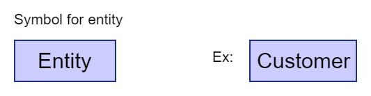
Usually, a business is made from people and data. And these data are usually a noun. For example, in an educational institution, there may be students, and staff, courses, fees, and much more. As such, it is fair to say the collection of these things or nouns makes the business or the enterprise whole. Being that as it may, among the collection of things, if we single out one type of noun, for example, students can be considered as an entity. In other words, either a physical thing or a fact or rather a concept in a business or an enterprise can be defined as an entity.
An entity can be a person, an object, a place, an event, or a concept in a business or an enterprise. Usually, when naming an entity, we use the singular form of the noun.
Examples:
- Person – Student, Employee, Lecturer, Doctor
- Object – warehouse, merchandise, vehicles, product
- Place – Store, Branch office, Building
- Event – Registration, Selling, Deposit, Withdraw
- Concept – Course, Payments
In ER diagrams, entities are shown as rectangles.
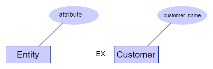
2. Attributes
Attributes describe the properties of an entity or rather in a sense an entity can be considered a table and attributes fields of the table. There are few types of attributes that you need to know and in an ER diagram, attributes are represented in oval shapes.
Other types of attributes,
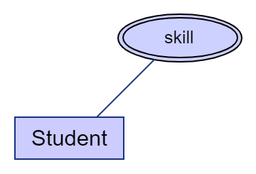
a. Multi-valued attributes
A multi-valued attribute is when an attribute has multiple values for an instance. Let’s consider a student, if you are asked to store his/her skills in a table, you might have to add a few skills under the same entry.
For example, Tom can sing and he is good at martial arts as well. In this case, the attribute “Skill” has multiple values within it.
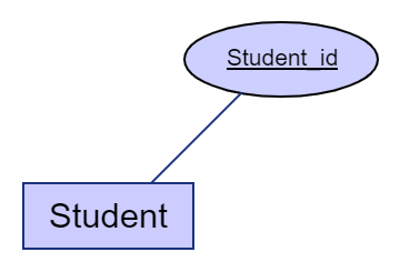
b. Key attribute
The key attribute is the unique attribute that helps to identify the designated entry in the entity table from the other records. For example, from giving a unique id for each student in a student set, you can identify any student separately from their id.
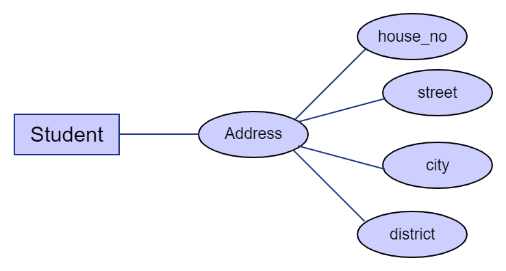
c. Composite attribute
An attribute that is made from a collection of other attributes is called a composite attribute. For Example, consider a situation where you are storing the addresses of the students.
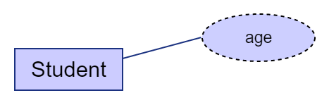
d. Derived attribute
A derived attribute is an attribute that is calculated, generated, or derived with the help of another attribute. For example, a student’s age can be derived from the birthday of the student.
3. Relationships
A relationship describes the association between two or more entities. There are four main types of relationships between entities.
- Unary Relationships.
- Binary Relationships.
- Turnery Relationships.
- N-ary relationships.
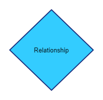
Relationships are represented in ER Diagrams using a Diamond shape. The relationship is written using a verb or a verb phrase inside the diamond shape.
Before diving into more details, let’s consider these relationships one by one.
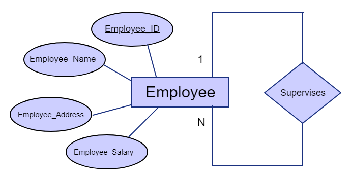
a. Unary Relationship
The unary relationship is also called as a recursive relationship. This relationship occurs between the instances of the same entity set. In this particular case, since it is the same entity set, the primary and foreign keys stay the same. However, it represents two separate roles within the same entity.
For example, consider a situation where a supervisor of a company has to supervise his subordinates. In this scenario, both the subordinates and the supervisor are employees under one company. Additionally, in this case, the supervisor is entitled to supervise one or more subordinates.
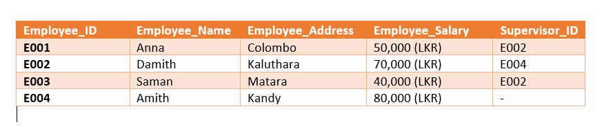
Relational Schema:
Employee(Employye_ID, Employee_name, Employee_Address, Employee_Salary, Supervisor_ID)
If we were to include these data in a table, it would be as follows.
b. Binary Relationships
Binary relationships describe the relationship between two entities. Binary relationships can be represented in three types.
- One-to-one Relationships.
- One-to-many Relationships.
- Many-to-Many Relationships.
As such, we will be discussing these three types of relationships in detail.
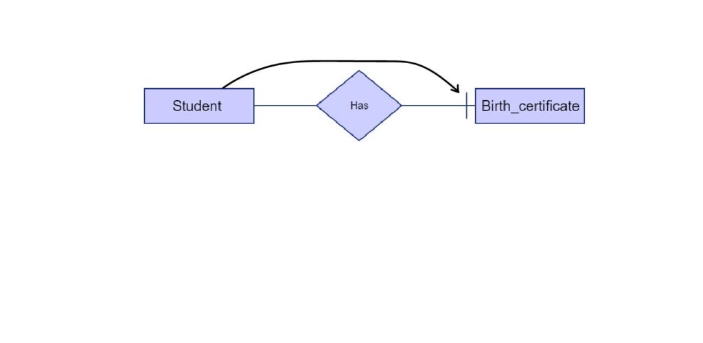
i. One-to-one Relationships.
In One-to-one relationships, one entity from entity set Entity-1 is associated with one entity from Entity-2. In the simplest terms, when the tables are drawn, a single record from Entity-1 has a single corresponding record in the Entity-2.
(As such, please note that you can draw both tables as one table if it is required. Since there is only one corresponding record per subsequent record, it will not alter the data structure by compacting both entities into one)
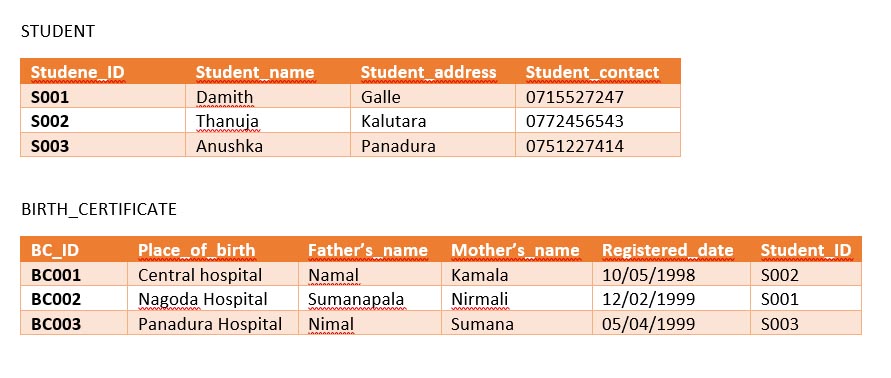
Please note that when choosing where to place your foreign key, in one to one relationships, place the foreign key on the child entity or the dependent entity. In this case, the student is the parent entity while the birth certificate is the child entity.
For example, let’s consider a situation where the birth certificate details of a student have to be recorded.
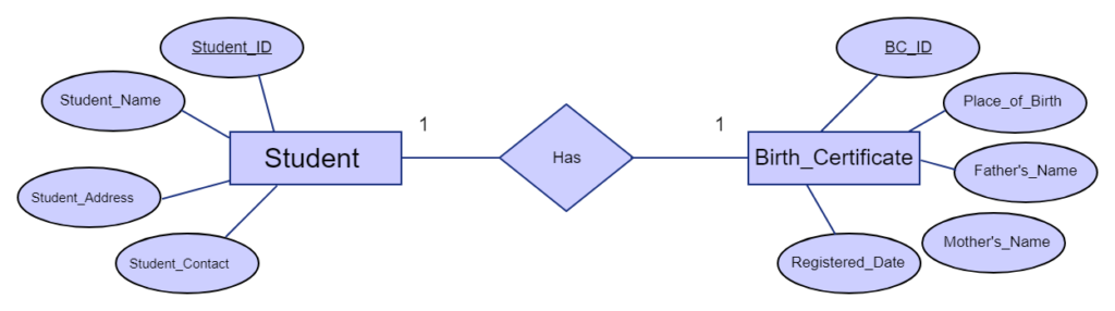
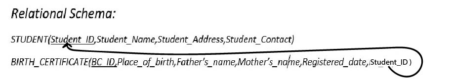
Table:
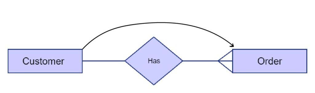
ii. One-to-many
One-to-many describes a relationship where one entry from Entity-1 has more than one corresponding entries in the Entity-2.
Please note that when you are placing the foreign key, you have to place in in the entity where many entries are available.
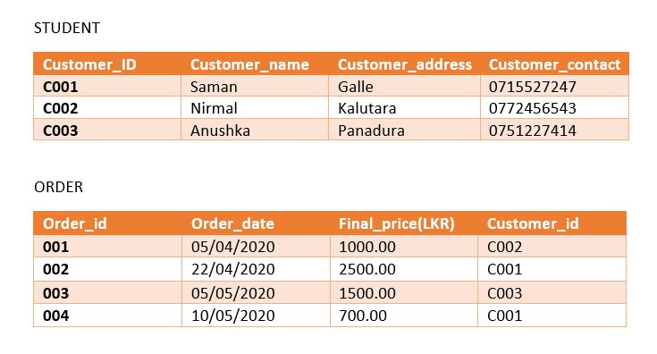
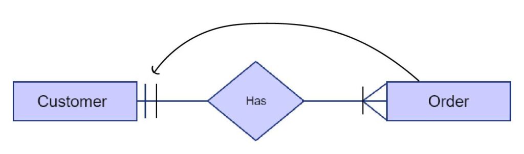
For example, let’s consider a situation where a customer places an order in a grocery shop. In this situation, one customer can make multiple orders as he/she may deem fit.
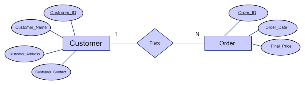
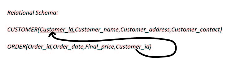
Table :
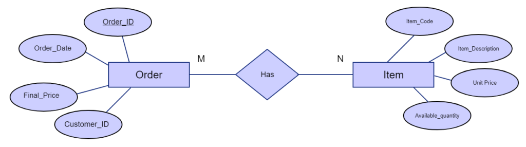
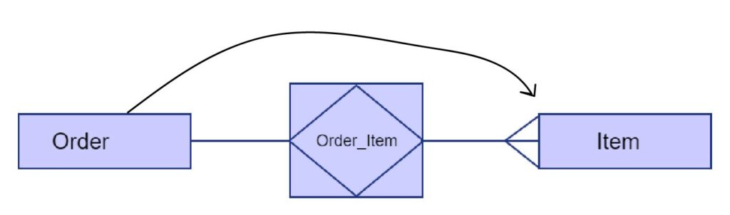
iii. Many-to-many relationship
In many to many relationships, we describe a relationship where many entries from Entity-1 has more than one corresponding entries in the Entity-2 to a ratio of M: N.
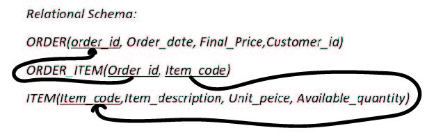
Please note that in this case, when we are placing the foreign key, we cannot directly use the exact relational model. We have to use an additional table to maintain data consistency.
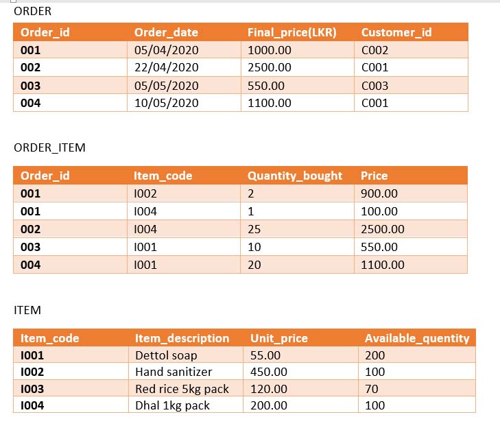
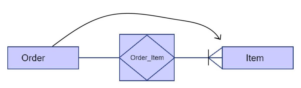
For example, consider an instance wherein a grocery store one order has multiple items, and since the item batch is stored in their warehouses the same item can be ordered more than once in different quantities.
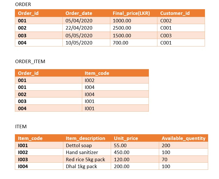
However, in this particular case, what we have already drawn is rather impractical since the given scenario indicates that there might be multiple quantities of the same item could be included in a single order.
That being the case, we can utilize the ORDER_ITEM table and add a column “quantity_bought” so that the contained data would be more meaningful. Additionally, we can calculate the price per item bundle of the same kind.
When we add additional attributes to the relationship, it becomes an Associate entity.
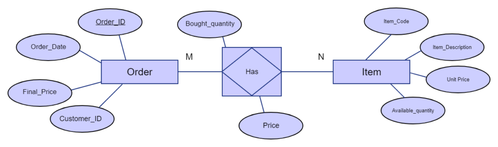
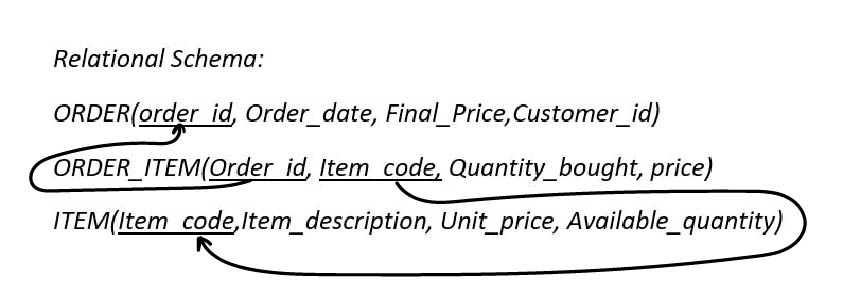
Table :
Note: Unary and Turnery relationships will be discussed in separate articles in the future.
Since these relationships between entities are clearly to be represented, we must represent one-to-one, many to many relationships. Thus, we mark both Cardinality and Ordinality. We will be learning crowfoot representation for cardinality.
1. Cardinality
Cardinality is the maximum number of records that Entity-2 can have corresponding to a single record of the Entity-1. We always mark the cardinality of the corresponding entities related to the selected entity relatively.
Let’s consider the earlier examples that we discussed under Binary Relationships.
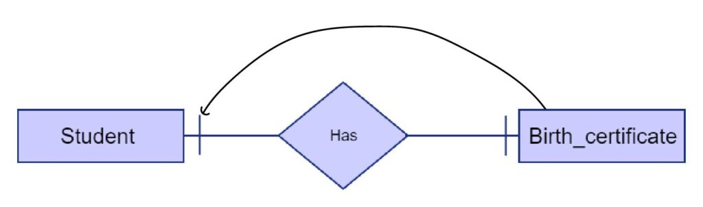
Example 1: one to one.
In this case, the maximum number of birth certificates a student can have is one.
The maximum number of students that a birth certificate can have is also one.
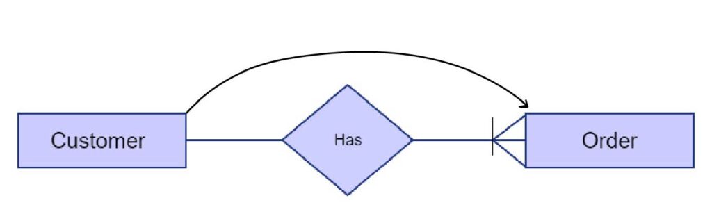
Example 2: One-to-many
A customer can place as much as orders he/she wants.
The maximum number of customers that a single grocery order can have is one.
Example 3: Many-to-many
In this case, an order can include many items.
As the items recorded consists of a large quantity of the same type of item, a type of item can be ordered more than once.
2. Ordinality.
Ordinality is the minimum number of corresponding entries of Entity-2 that exists in the Entity-1. This is also marked in the same relative method we used while marking cardinality. We mark ordinality in front of cardinality.
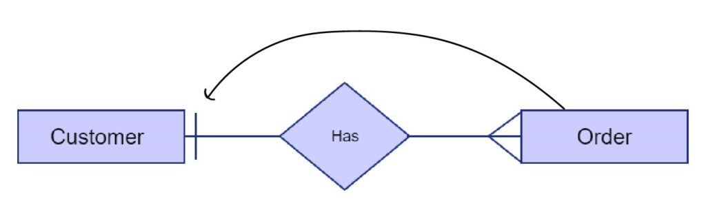
Example 1: One-to-many
In this case, to add a customer, he must buy something from the store. So to be a customer having at least one order is mandatory.
It is the same for orders too. An order cannot exist without a customer. So, for an order, a customer is mandatory.
Example 2: many to many.
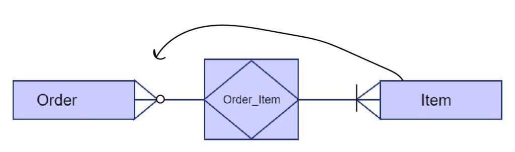
In this case, an order should have at least one item, so an entry in order entity must have at least one item.
However, it is not mandatory for an item to have an order, because there may be items that might not sell. So, the not mandatory indicator is placed in front of the cardinality as a small circle.
After cardinality, you must have a basic understanding of “Total Participation” and “Partial participation”
Partial participation.
In partial participation, the entities in the entity set may or may not participate in the relationship set, which is why it is called optional participation.
It is represented using a single line between the entity and relationship sets.
Let’s consider an example where a student enrolls in a course program.
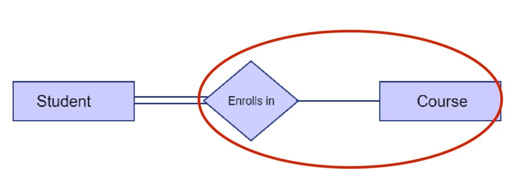
In this case, students don’t need to enroll in all the course programs, which in the sense, there might be course programs that students did not sign up for.
Total participation.
In total participation, it states that the entities in the entity set must participate in the relationship set, which is why it can also be said mandatory participation.
It is represented using double lines between the entity and the relationship.
Let’s consider the above example again.
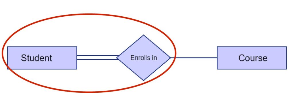
In this case, the student must enroll in at least one course
In a sense, Ordinality can indicate whether the participation is partial or total.
Note: The next article will be tips for drawing ER Diagrams.